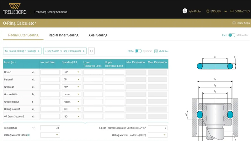
Info ORing Compression (%) info Free Groove Volume (%) info ORing Inner Diameter Stretch (%) info Groove Depth incl Gap (mm) info Sealing Gap (mm) Calculated Values at Excentrical Position of Piston ORing Compression (%) Groove Depth incl Gap (mm) Sealing Gap (mm)Static and dynamic Oring seal design differs in a few key ways A static Oring is any oring designed to contact with two or more surfaces that do not move relative to one another, whereas a dynamic Oring is one that helps form a seal between moving parts On the whole, static orings are created from less robust and hard Oring seals are not recommended, therefore, for speeds less than one fpm when pressure differentials are below 400 psi If system pressure slowly diminishes, as through slow valve leaks, and a

Cartridge Seal An Overview Sciencedirect Topics
O-ring shaft seal design
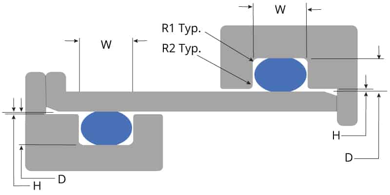
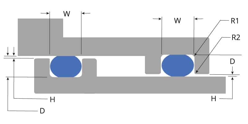
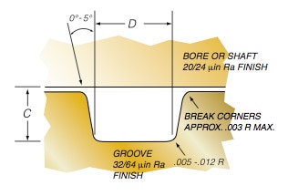
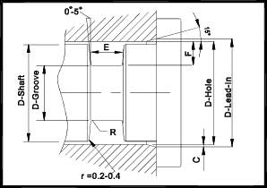
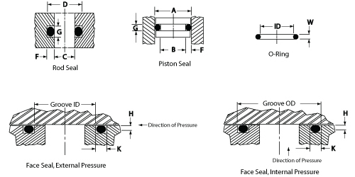
O-ring shaft seal design-O'ring Groove Design As important as the o'ring seal itself is the groove that the o'ring seats into The groove must be designed to accommodate not just the o'ring size, but also its intended usage;Freudenberg Sealing Technologies offers market leading sealing solutions for all industries and applicationsUse our eCatalog to find the right application for your specific requirements No matter if you require a Simmerring, oring, rod seal or another solution, we have the right component available for you


What Is An O Ring Selection Material And Storage Barnwell
Shaft seals and packings Our products address the needs of customers that wish to have a broad range of products and solutions at hand The company was founded in 1963 as Mogens Christensen, Ingeniør& Handelsfirma A/S We are undergoing a rapid period of development and we now have 5,000 m of offices, lab,2 production and warehouses at our disposal Our branch inCall Us Seal & Design Canada Toronto, Ontario (416) Toll Free Headquarters Clarence, NY (716) Higbee Division Syracuse, NY (315) Email Us Seal & Design Canada Toronto, OntarioSKF industrial shaft seals and accessories are divided into three main groups • Radial shaft seals • Axial shaft seals and • Wear sleeves Different seal types within these groups are described with their respective design, materials and applications Product descriptions are followed by product tables It should be noted, however, that
The seal eff ect of the Oring is created by the elasti c deformati on of its crosssecti on (d 2) in an appropriately designed installati on space or slot This means that the circular crosssecti on is deformed to become ellipti cal, which closes the gaps between the contact surfaces and at the ground of the groove This Some installation lubricants can dry and cause seals to stick to the shaft, leading to high friction or seal twisting Don't Underestimate the effects of rapid stretch on sealingOur challenge is to design seals that are able to withstand a wide range of media, diff erent aggregate states and varying pressure and temperature and to provide special solutions for small installation up to seal contact areas of several meters Every application has its own special requirements profi le, and our job is to provide the best sealing solution The EagleBurgmann
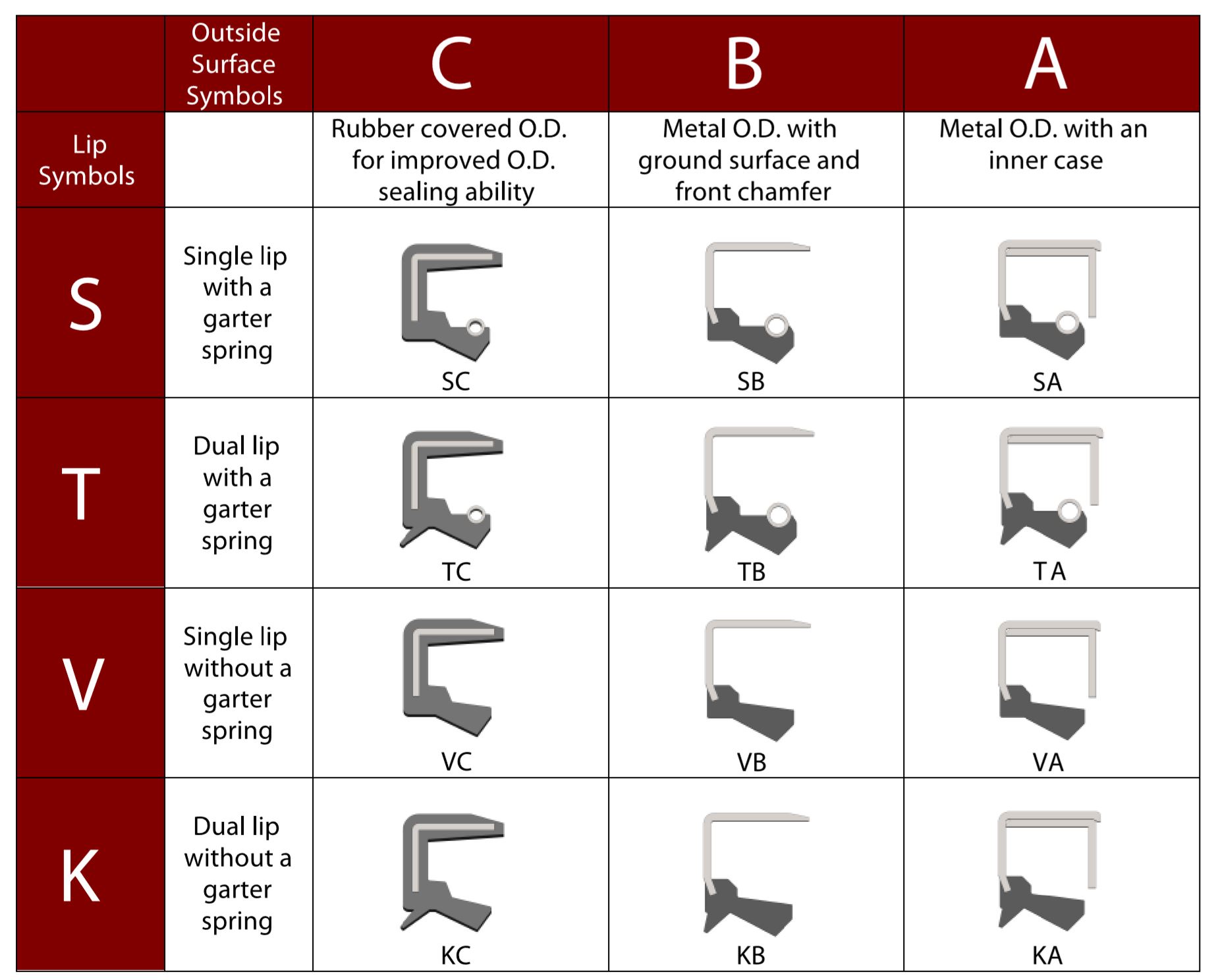
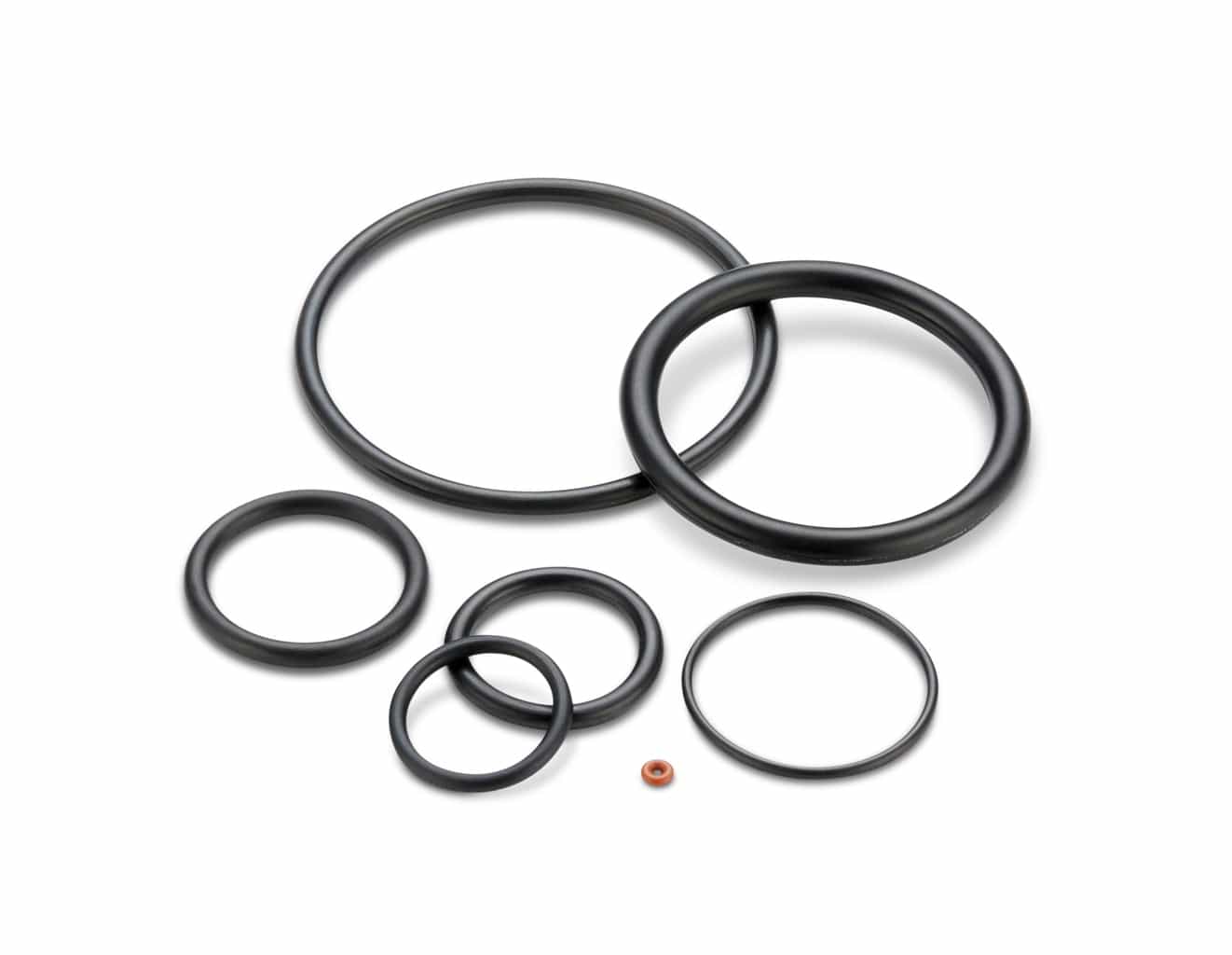
O'Ring Kits (Metric) Shaft Seals Inch SC SB2 S TC TB2 T VB VC KB KC Metric SC SB2 S TC TB2 T VB VC BABSL O'Ring cord can be used to manufacture custom O'Rings when no standard size is available A wide variety of crosssections and sizes are available ED DIN Connector Rings Nitrile /N 65/225F 54/107C Fluorocarbon /V65/225F 54/107C EthyleneIt is a loop of elastomer with a round crosssection, designed to be seated in a groove and compressed during assembly between two or more parts, creating a seal at the interface The Oring may be used in static applications or in dynamic applications where there is relative motionWelcome to our Oring Seal Design section This Oring seal design section will give you step by step instructions on how to design a seal or rubber part for your application Consider this a rubber guide or Oring guide in helping you find the exact rubber material and size you need Some parts of this online rubber or Oring design guide can be downloaded in PDF but everything can just be


Oring Ehandbook


Hydrapak Seals Products O Rings Size Dimensions
Orings are used primarily for sealing The various types of Oring seals are described in this section under "Scope of ORing Use" Orings are also used as lightduty, mechanical drive belts More information, including design criteria on Oring drive belts and their application will be found in ORing Applications, Section IIIRubber Seals, Sealing Devices & ORing Seal Design AppleOrings are the epitome of elegant engineering The ring itself costs only a few cents, and the groove it goes in is simple and easy to manufacture But desp


Rotary Shaft Seal Shaft Seals American High Performance Seals


Inch And Metric Oil Seal Types Gbsa Oil Seal Manufacturers
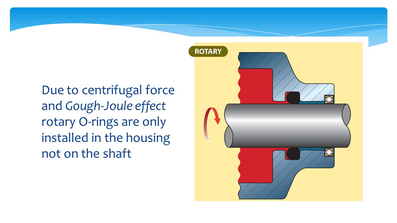
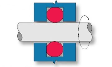
Viele übersetzte Beispielsätze mit "o ring shaft seal" – DeutschEnglisch Wörterbuch und Suchmaschine für Millionen von DeutschÜbersetzungenDesigning the parts of an application where orings will be applied is broadly termed "oring groove design" In order to seal properly, the oring has to deform in the application by being compressed and stretched in any number of ways The design of the groove where the oring sits plays a major role in how the oring performs its sealing roleIn most rotational shaft applications, Oring squeeze should be kept to as little as 0002" by using an Oring with an OD of about 5% larger than the accompanying gland Once installed, peripheral compression puts the Oring's ID in LIGHT CONTACT with the turning shaft This design minimizes frictional heat buildup and prolongs seal life


Vane Shaft And Seal Design The Critical Difference In Pneumatic Rotary Valve Actuators Kinetrol Pneumatic Rotary Vane Actuator Blog


Shaft Seal Ksb
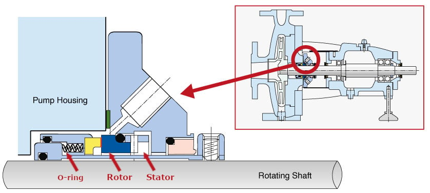
Most orings are designed to operate at pressures up to 1,500 psi At higher pressures, the material must have enough strength to resist extruding into the clearance gap The chart shows the recommended combined limits of clearance, gap, material hardness andIn an Oring seal, sealing between the rotating shaft and the rotating seal face is effected by an Oring (figure 139) grundfoscom grundfoscom In einer ORingdichtung wird die Abdichtung zwischen rotierender Welle und rotierender Dichtungsfläche durch einen ORing erreicht (Abbildung 139) netgrundfoscom netgrundfoscom These extremely robust cases with7 Zeilen If the bore or shaft size you are using is not listed, select the ORing with an inside diameter just smaller than the shaft you are using If you are designing a face seal, select the ORing with an inside diameter which will position the ORing on the side of the groove opposite the pressure Click here for more information on face seal groove design Note the ORing inside


O Ring Groove Design Global O Ring And Seal


Rotary Seals Design For Construction Machinery Dms Seal Manufacturer
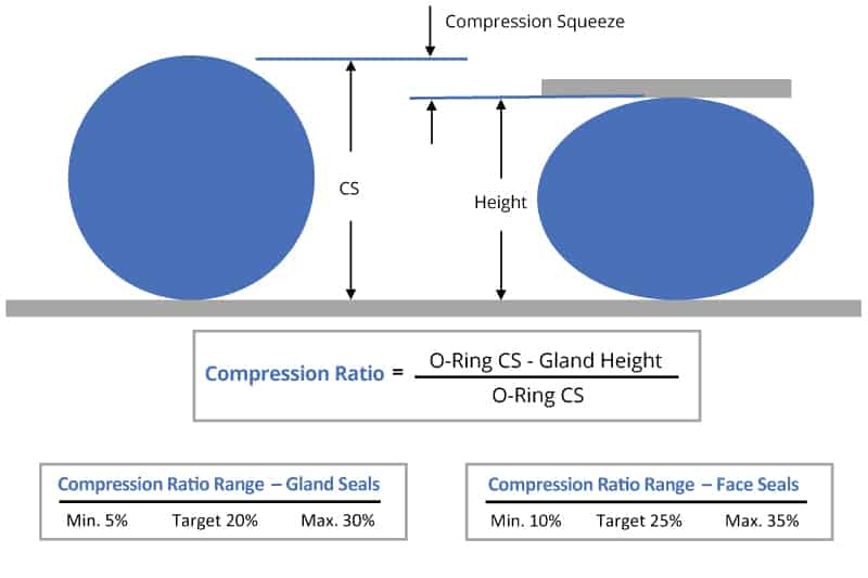
Additional HDS design options ;'O' Ring Guide Introduction The 'O' ring, or toroidal seal, is an exceptionally versatile sealing device Applications, ranging from garden hose couplings to aerospace or oil and gas duties, make it the world's most popular volumeproduced seal 'O' rings offer many benefits to designers, engineers, maintenance staff and plant An Oring forms a seal when it is squeezed between two adjacent surfaces As the ring is squeezed, a contact stress between the Oring and the surfaces emerges If the fluid pressure is lower than the contact stress, then the seal prevents the fluid from escaping


All Seals Inc The Sealing Specialists


Www Pressureseal Com Orings Oguide Pdf
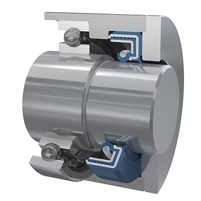
The oring seal design process begins with understanding the gland type in which the seal will be seated To ensure the oring fits properly it is recommended that the oring is stretched 1 to 5% circumferential, with ideal stretch at 2% Further considerations listed below include;Rotary FlexiSeals feature either a flanged design or an O Ring on the OD to keep the seal fixed in the bore as the shaft rotates The ORing can either be centred along the OD or be located in the heel of the seal Virtually any O Ring material can be supplied with a custom rotary FlexiSeal, but a fluorocarbon material is standardBy selecting it to be slightly less than the


Metric O Ring Groove Design Reference Guide


What You Need To Know About Dynamic Seal Applications Hot Topics
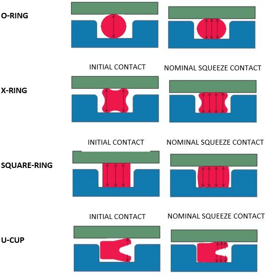
ORing Seal Design Standard AS568 ISO 3601 Example ASN Nitrile Oring (AS Size 0070 CS x 0614 ID) Oring Standards Oring Search Tools Measured on ShoreA hardness index Shore A = Rubber Band Shore 40A = Pencil Eraser Shore 60A = Car Tire Tread Shore 70A* = Running Shoe Sole Shore 80A = Leather Belt Shore 100A = Shopping Cart WheelGland Designs for QuadRings®/XRings Therefore Oring seals are not recommended for speeds less than 1 foot (0,3 m) per minute when the pressure difference is less than 400 psi (27,5 bar) A good solution to avoid spiral failure is the use of QuadRings®/XRings QuadRings®/XRings are used in many dynamic applications where Orings provide less than satisfactory performanceThe tendency of an Oring to return to its original shape when the cross section is deflected is the basic reason why Orings make excellent seals The squeeze or rate of compression is a major consideration in Oring seal design Elastomers may take up the stackup of tolerances of the unit and its memory maintains a sealed condition


Http Practicalmaintenance Net Wp Content Uploads Working Design Considerations And Maintenance Of O Rings Pdf


O Rings Archives Polymax Blog
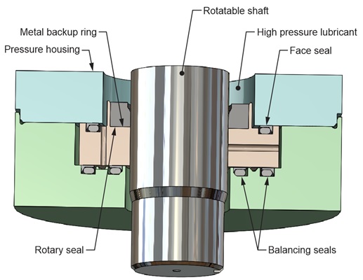
In mechanical face seals, elastomers tend to take second chair because the primary seal—the dynamic seal between the housing and rotating shaft—is achieved by sliding contact between the pair of stiffer, lappedflat sealing faces, one stationary in the housing and one rotating with the shaft In many designs, rubber provides the secondary seal between each seal face5314 ORing Glands for Rotary Seals Design Chart 54 provides the basis for calculating gland dimensions For standard Oring sizes, these dimensions have been calculated and are listed in Design Table 54 The procedures for the use of Design Table 54 are outlined in DesignAn instructional video on how to assemble an oring seal on a 40K cell piston rod


1


Design Of O Ring Seals Ppt Video Online Download
ORing Groove design plays an important part in how an oring seals Learn More > Contact World Class;Dynamic Rotary ORing Gland Design In a dynamic rotary seal applications a turning shaft protrudes through the ID of an oring, the oring then becoming a seal The table below lists recommended dimensions for dynamic rotary seal glands by AS568A oring dash numbers Static Radial Glands Axial Internal PressureReciprocating seals are a dynamic version of either a male radial or female radial Oring design In a reciprocating seal, there is relative reciprocating motion (along the shaft axis) between the inner and outer elements This motion tends to slide or roll the Oring, or sealing surface of the Oring, back and forth with the reciprocal motion Examples of a reciprocating seal would be a


Shaft Seals For Rotating Shafts


Buna O Ring O Ring In Houston And Minneapolis Dichtomatik
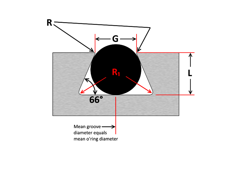
Seal gland type, sealing application (fluid, solid gas), pressures, operating temperatures, and chemicalMarco Rubber offers a wide variety of high pressure oring materials for use with or without backup rings or consider metal spring energized PTFE seals for ultimate high pressure sealing performance Need help, contact an application engineer for assistance in selecting the best high pressure oring materials or product selection or groove design assistance from our expert teamDESIGN DIMENSIONS FOR ORING INSTALLATION Orings are normally used as seals in several ways, and dimensions of the groove or gland will also vary with the cross section of the ring, the type of operation, and the amount of pressure used in the system These dimensions will also be different if the Oring is sealing a liquid which has a low volume


O Ring Groove Design Sealing Australia
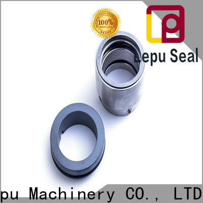


Pool Pump Shaft Seal O Ring Seal Design Lepu
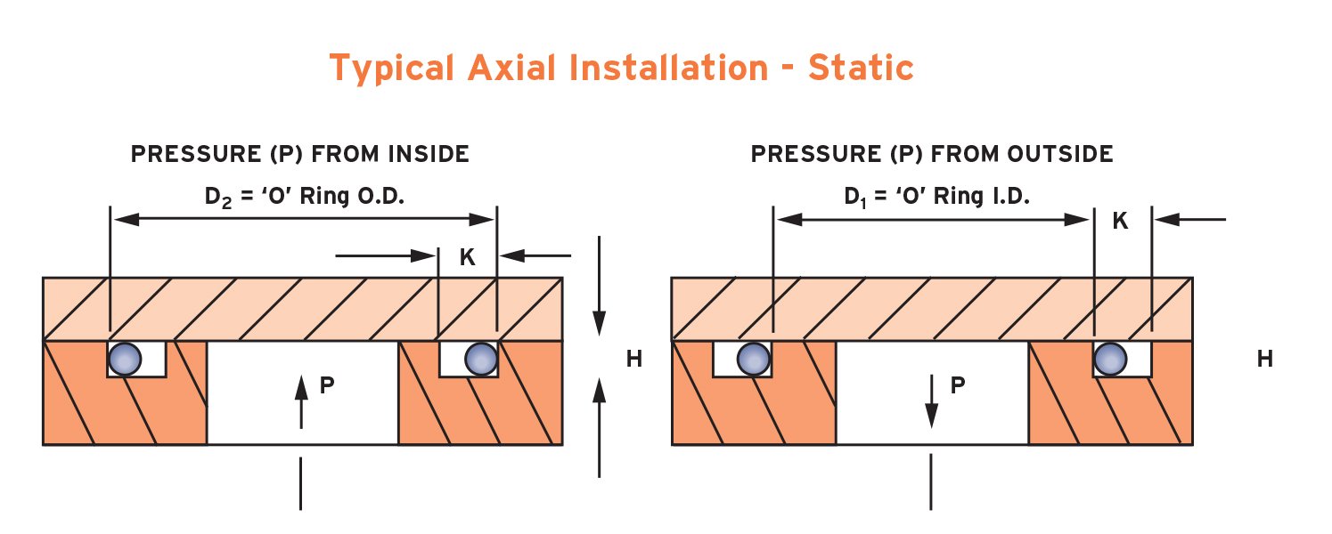
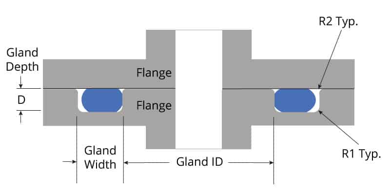
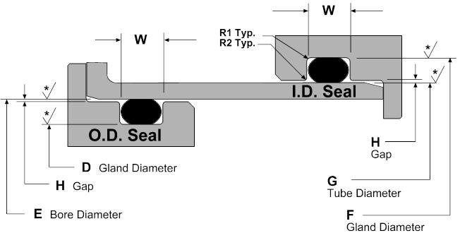
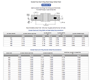
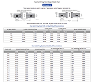
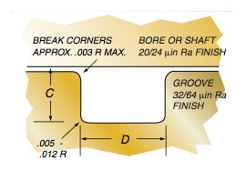
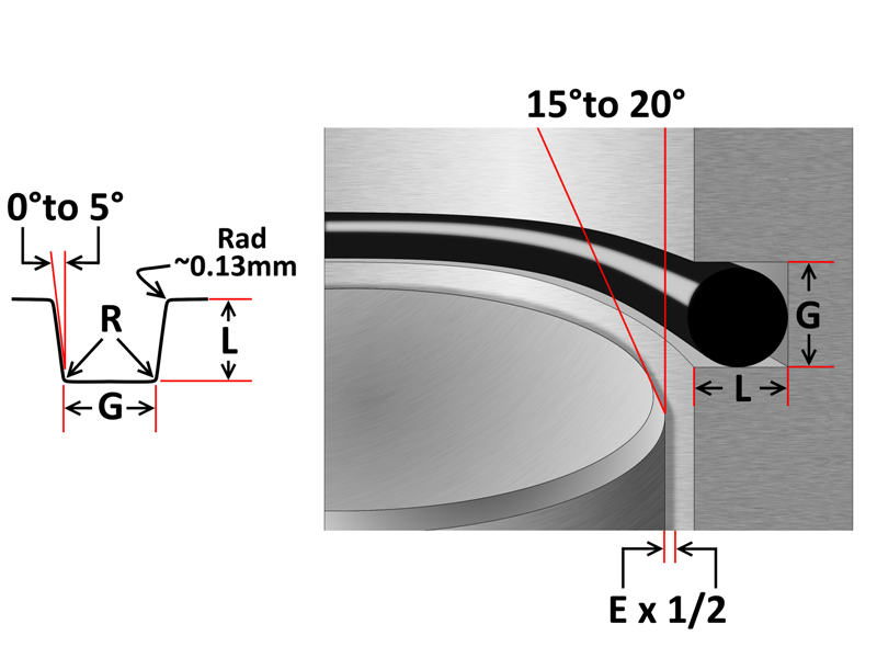
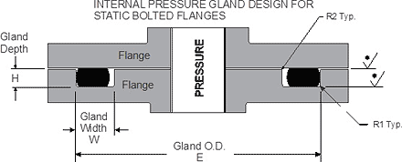
Oring seal The tables at the right and the diagram below provide the recommended gland design parameters In addition, the gland surfaces must be free from all machining irregularities, and the gland edges should be smooth and true and free of nicks, scratches, and burrs A perfectly designed Oring seal is of little use if the OringBe it dynamic or static operation, radial or axial loading, vacuum or high pressureStatic oring face seals, used for a wide variety of applications, come in many shapes and forms Whether you need bolted flanges or removable lids, this oring face seal groove design guide will help you choose the right oring for your application ORing Size Charts Oring, xring and square ring size charts
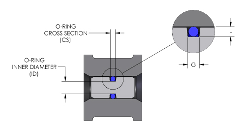


O Ring Groove Design O Ring Groove Dimensions Mykin Inc


1
What is the difference between static and dynamic Oring seals?Piston seal (figure 36) the ORing is inserted in a seat machined on the component which constitu tes the shaft of the assembly, and the preloading deformation for the seal is of a radial type;Groove Design ORing Seals for Static and NonRotary Dynamic Applications Speak to an Engineer About Your Project Crosssection Select an ORing crosssection size from the available standard sizes If you are unsure what crosssection size to use, see here Clearance Determine the maximum clearance present in your application For a radial seal, subtract the minimum rod (shaft
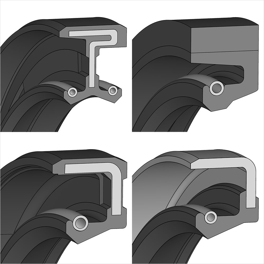


Radial Shaft Seals Freudenberg Fst


How To Measure And Identify Oil Seals Polymax Blog
Flange seal (figure 37) the ORing is compressed between two flat parallel surfaces and subjected to preloading deformation of an axial typeOring, seal tips mechanical shaft mechanical seals pneumatic seals abrasion orings extruded rubber low temp seals oil seal materials oil seal basics FEP/PFA encapsul 1 FEP/PFA encapsul 2 neoprene oring nitrile oring lathecut oring acid orings hydraulic seals high temp seal rubber oring metric sizes Glossary of termsRadial shaft seals with a low cross sectional height Cassette seals Wear sleeves Track pin seals Metal face seals Vring seals Axial clamp seals Sealing and spacing washers Hydraulic seals General technical information Piston Seals Rod and buffer seals Wiper seals Guide rings and guide strips Orings and backup rings Fluid
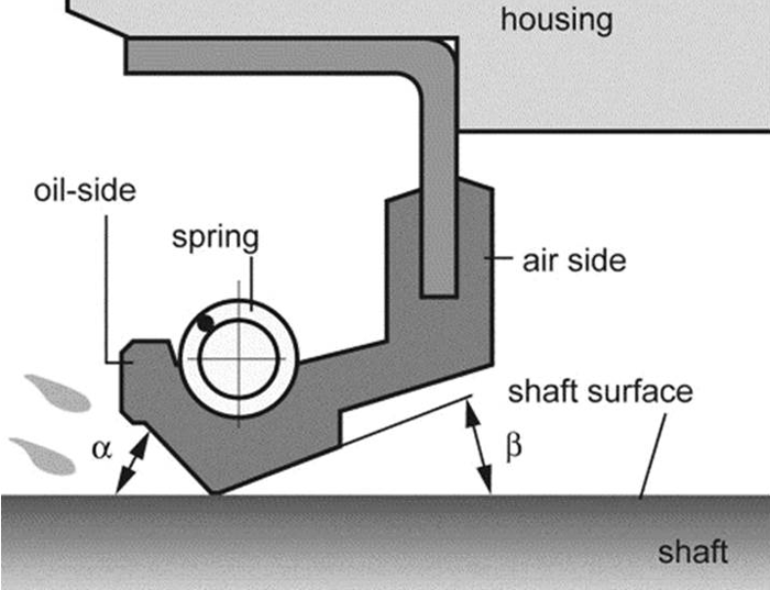


Shaft Seals For Rotating Shafts


Your Guide To Choosing The Best Rotary Shaft Seal
An Oring, also known as a packing or a toric joint, is a mechanical gasket in the shape of a torus;ORing design for axial seals is similar to that for radial seals, with the important points summarized below The ORing must be compressed by a predetermined amount, and this compression determines the ORing crosssection diameter The ORing inner diameter is typically chosen to be close to the groove's inner diameter;Oring seals are typically used for sealing spool valves and for pistons in pneumatic cylinders and similar reciprocating applications Two regimes are possible • With radial compression of the Oring The ring is compressed radially in its groove, with a compression of the crosssection of from 2% to 6%, according to thickness


O Ring Groove Design Global O Ring And Seal


Cartridge Seal An Overview Sciencedirect Topics
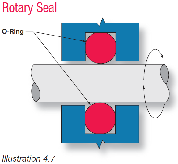
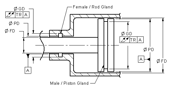
There are two types of radial designs 1 Male or Plug the Oring groove is located on a plug which is inserted into the housing or cylinder (fig 123) 2 Female or Tube the Oring groove is located in the housing or cylinder and a tube is installed through the Oring lD (fig 124) Male or Plug Seal design is based on An engineering design flaw in the Oring seal on one of the solid rocket boosters caused a leak of hot gas that eroded the external fuel tank and led to the explosion The leak was exacerbated by unusually cold weather the night before the launch, which caused the Oring to lose elasticity and form a bad seal Almost no one realized that this might be a problem until itAn Oring has proved to be a practical rotary shaft seal in many applications With the correct design, Parker ORing rotary seal compound N, will provide satisfactory service at surface speeds up to 1500 feet per minute The design conditions are most critical for rotary seals, as would be expected Relatively high durometer compounds,


Fundamental Of O Ring


Static O Ring Design Chart Marco Rubber Plastics Custom O Rings Supplier


Metric Oil Seals Shaft Seals Oil Seals Houston


Sealink Sealing Mechanism Lubricant Free Mechanical Seal Design Sealink


Http Practicalmaintenance Net Wp Content Uploads Working Design Considerations And Maintenance Of O Rings Pdf


Diagram Of The Face Seal Design 1 Seal Ring Flexibly Attached 2 Seal Download Scientific Diagram


Balance In Mechanical Seals Choosing Pumps For Condition Monitoring Pumps Systems


Water Seal Rubber V Seal V Ring Va Vs Vl Rotary Shaft Seal Ring Buy Rubber V Seal Vs Ring V Seal Product On Alibaba Com


Oil Seals Radial Oil Seals Trelleborg


Seal Design O Ring Design O Ring Design Guide


V Rings All Seals


O Ring Groove Design Global O Ring And Seal


Groove Design O Ring Seals Minnesota Rubber Plastics


Carbon Graphite Mechanical Seal Types


Mechanical Seals Totally Seals
.jpg)


Wave Springs Improve Mechanical Seal Design


Fundamentals Of Mechanical Seals Seal Faqs


What Is An O Ring Selection Material And Storage Barnwell


Oring Ehandbook


What Is A Mechanical Seal Aesseal
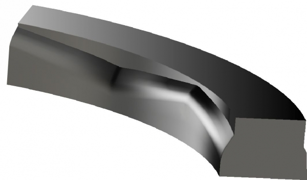


Kalsi Seal Introduction High Pressure Shaft Seal Designs
.jpg)


An Introduction To Ptfe Lip Seals For Rotary Applications
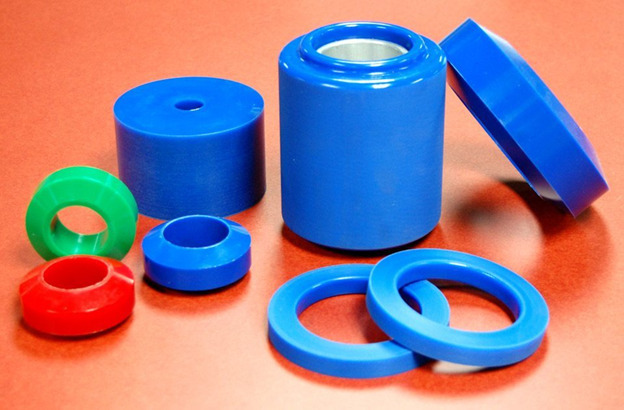


Types Of Seals A Thomas Buying Guide


O Rings O Yeah How To Select Design And Install O Ring Seals Tarkka


Dynamic Rotary Gland Design Dynamic O Ring Gland


Dynamic Reciprocating Gland Design Dynamic O Ring Gland
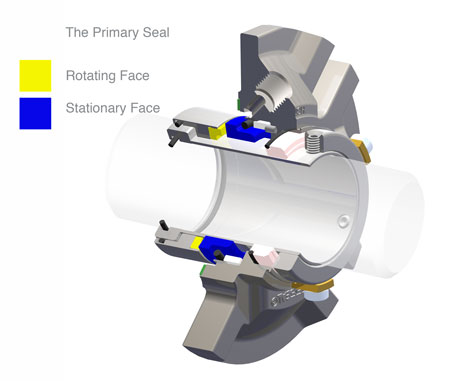


What Is A Mechanical Seal Aesseal


Rotary Sealing Solutions Radial Oil Seals And V Rings Youtube
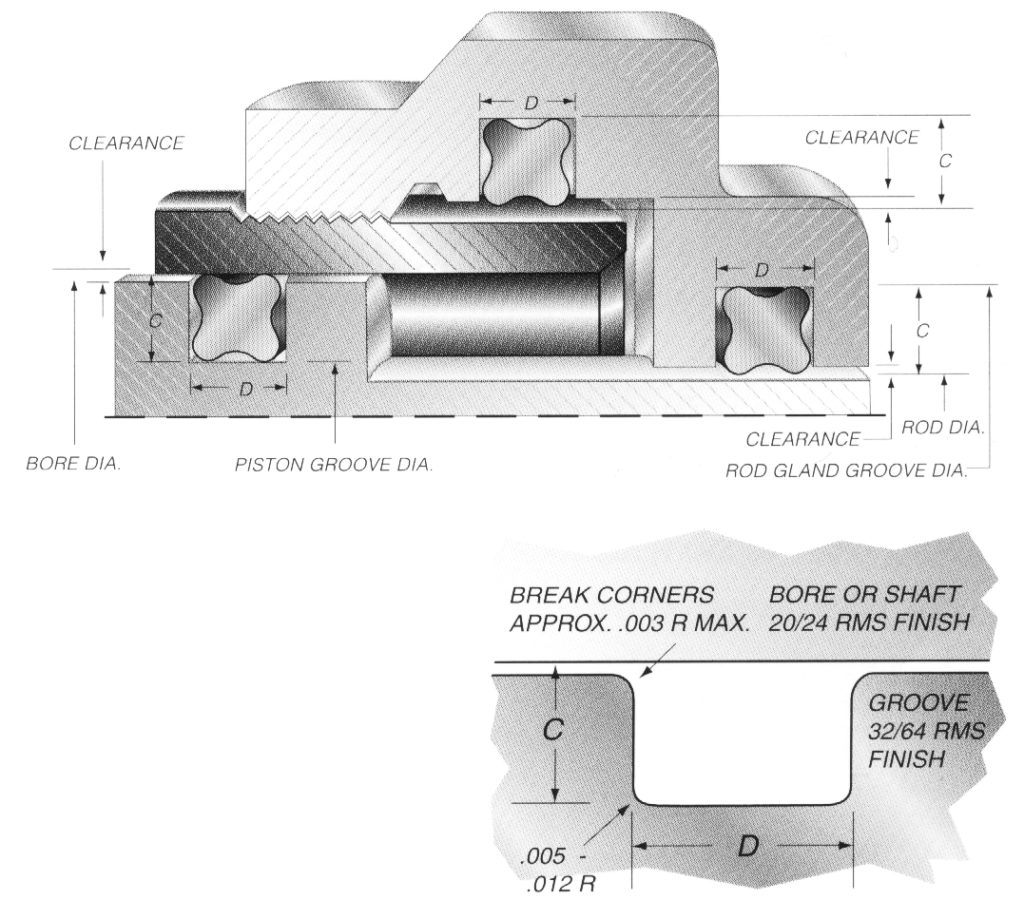


Quad Ring Groove Design Daemar Inc


O Ring Groove Design Seal Design Inc


V Ring Seals Seal Design Inc
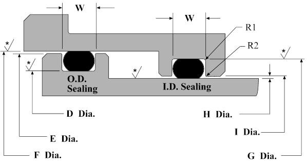


Dynamic O Ring Design Chart Marco Rubber Plastics Custom O Rings Supplier


Single Seals For Caustic Environment In Pumps


Seal Solutions Guide


Rotary Shaft Seals Seal Design Inc
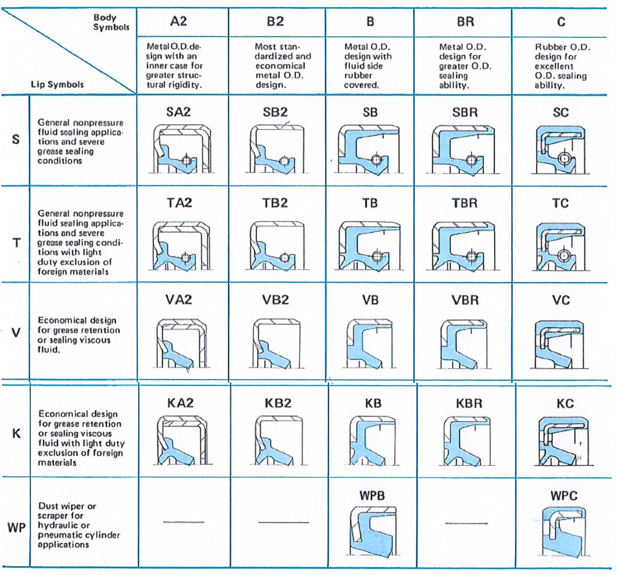


Oil Seal Design Selection Gbsa Inc
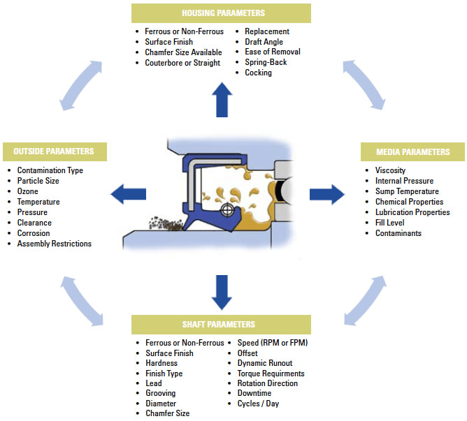


Dynamic Seals Selection Guide Types Features Applications Engineering360
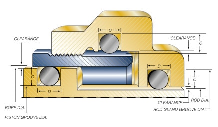


Groove Design O Ring Seals Minnesota Rubber Plastics


O Ring Groove Design Guides Engineering Quick Reference


O Ring Groove Design Guides Engineering Quick Reference


O Ring Calculator Trelleborg Sealing Solutions


What You Need To Know About Dynamic Seal Applications Hot Topics


Groove Design O Ring Seals Minnesota Rubber Plastics


1


What You Need To Know About Dynamic Seal Applications Hot Topics


O Ring Installation Design And Specification For Dynamic Applications Engineers Edge


Shaft Seals Trelleborg Sealing Solutions Youtube


Protech Bearing Isolator Made By Parker The Hope Group Largest Parker Distributor In New England


Shaft Seal Ksb


Radial Shaft Seals Dynamic Rotary Lip Seals Freudenberg Fst


1


O Ring Seals Roy Mech


O Ring Groove Design Daemar Inc


Rotary Sealing With High Pressure Seals Kalsi Engineering


O Ring Wikipedia


O Rings O Yeah How To Select Design And Install O Ring Seals Tarkka


Www Hitechseals Com Includes Pdf O Ring Brochure Pdf


O Rings O Yeah How To Select Design And Install O Ring Seals Tarkka


Seal Solutions Guide


Types Of O Ring Applications


Oring Ehandbook


O Ring Shaft Seal Design Dms Seals


O Ring Groove Design Global O Ring And Seal


Oil Seals Seal Design Inc


Duramax Marine Shaft Sealing Systems Drymax Stern Tube Seals


Engineering Seals Seals For Rotating Shafts


What Are Rotary Shaft Seals Cinchseal


Quad Rings All Seals


Mating Ring An Overview Sciencedirect Topics


Sealing High Speed Shafts In Turbomachinery Pumps Systems


Groove Design Quad Ring Seals Minnesota Rubber Plastics


O Ring Groove Design Sealing Australia


Www Applerubber Com Src Pdf Seal Design Guide Pdf


Static O Ring Face Seal Groove Design Guide
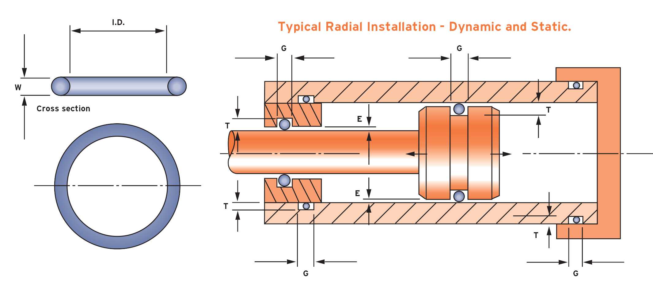


What Is An O Ring Selection Material And Storage Barnwell


What You Need To Know About Dynamic Seal Applications Hot Topics


0 件のコメント:
コメントを投稿